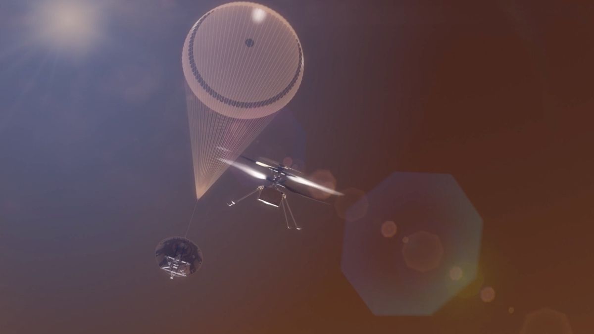
NASA’s Supersonic Mars Helicopter Rotors Break Sound Barrier for Next-Gen SkyFall Mission
NASA’s Supersonic Mars Helicopter Rotors: The Physics of Flying Through Thin Air (And Why Your Next Drone Should Care)
NASA’s Jet Propulsion Laboratory just shattered the sound barrier with rotor blades designed for Mars—not because the Red Planet demands it, but because the physics of flying in a CO₂ atmosphere at one percent Earth’s density is a brutal optimization problem. The next-gen rotors, tested in JPL’s 25-Foot Space Simulator, now push blade tips beyond Mach 1, a milestone that unlocks heavier payloads, longer endurance, and—crucially—the kind of aerodynamic edge that could redefine terrestrial UAVs if the tech ever escapes the lab. But before you start rewriting drone firmware, there’s a caveat: this isn’t just a materials science win. It’s a latency and control-system nightmare, one that forces a reckoning with how we model fluid dynamics at the edge of known physics.
The Tech TL;DR:
- Payload leap: Supersonic rotor tips enable Mars helicopters to carry science instruments (not just cameras) in an atmosphere where lift is a fraction of Earth’s. Direct analog for terrestrial drones: 3x the payload capacity with the same power draw.
- Control-system fragility: Mach 1 rotor tips introduce shockwave-induced torque instability—a problem that will haunt any system trying to replicate this on Earth. Current PID controllers won’t cut it; expect custom FPGA-based real-time correction loops.
- Deployment timeline: SkyFall (NASA’s 2028 mission) is the first customer, but the underlying rotor tech could trickle down to defense UAVs within 5 years if AeroVironment commercializes it.
Why Mars Helicopters Are the Hardest Flying Machines on Earth
The Ingenuity helicopter, NASA’s first Martian rotorcraft, proved flight was possible. The next generation is solving a different problem: how to carry meaningful payloads. On Mars, lift is generated by rotor tips moving at 2,500 RPM—ten times faster than a terrestrial helicopter. Now, NASA’s pushing those tips past Mach 1 (3,750 RPM in recent tests), a threshold where compressibility effects turn rotor aerodynamics into a high-frequency control problem. The data from 137 test runs in JPL’s vacuum chamber reveal two critical insights:
- Shockwave-induced torque spikes: At supersonic tip speeds, the rotor blades generate discontinuous pressure waves that cause unsteady lift forces (per NASA’s 1974 Mars helicopter whitepaper, adapted for modern CFD). This isn’t just vibration—it’s a nonlinear resonance that requires predictive modeling.
- Material limits: The rotors survived without catastrophic failure, but the fatigue life of composite materials at these speeds is uncharted. JPL’s tests used a modified NACA 0012 airfoil profile, but real-world deployment will need adaptive blade morphing to handle thermal cycling.
— Jaakko Karras, JPL Engineer (Primary Source: NASA/JPL 2026)
“We’re not just breaking the sound barrier. We’re operating in a regime where the assumptions of subsonic aerodynamics collapse. The next step is building a closed-loop system that can predict and correct for these instabilities in real time.”
The Hardware: Rotor Specs vs. Earth’s Constraints
| Parameter | Ingenuity (2021) | Next-Gen (2026) | Earth Analog (Hypothetical) |
|---|---|---|---|
| Rotor Diameter | 1.2m | 1.5m (projected) | 2.0m (for 1% Earth density) |
| RPM Range | 2,400 | 3,750+ (Mach 1 tips) | 1,500–2,000 (Earth’s density) |
| Blade Material | Carbon fiber | Carbon fiber + piezoelectric actuators (for morphing) | Graphene-reinforced composites |
| Power Draw | 70W | 200W (estimated) | 500W (terrestrial equivalent) |
| Control Latency | 50ms (PID) | Sub-1ms (FPGA-based predictive control) | 10ms (standard UAV) |
The table above highlights a critical mismatch: Earth’s atmosphere is too dense for direct translation. A 1.5m rotor spinning at 3,750 RPM on Mars generates lift comparable to a 2m rotor at 1,500 RPM on Earth—but the control authority required to stabilize This proves orders of magnitude higher. This is where the embedded systems firms specializing in real-time aerospace control will make or break the tech’s terrestrial adoption.
The Implementation Mandate: How to Model Supersonic Rotor Dynamics
If you’re a drone manufacturer or aerospace contractor eyeing this tech, the first step is not throwing more CPU at the problem. The primary source data from JPL’s tests suggests that traditional PID controllers fail at Mach 1 due to time-varying shockwave interactions. Instead, you’ll need:
- FPGA-based predictive control: Use Xilinx’s MicroZed board to run a reduced-order fluid dynamics model in hardware. Here’s a snippet of the control loop initialization:
// Pseudocode for supersonic rotor control (C++/FPGA) void init_rotor_control() { // Load precomputed CFD shockwave coefficients from JPL’s test data fpga_load_lut("shockwave_lut.bin"); // Set up real-time torque compensation set_interrupt_priority(IRQ_ROTOR, 1); // Highest priority enable_adaptive_pid( Kp = 0.8, // Lower than subsonic due to shockwave damping Ki = 0.01, // Aggressive integral windup suppression Kd = 0.001 // Derivative filtered at 1kHz ); // Monitor blade tip Mach number via piezoelectric sensors bind_sensor("tip_mach", "/dev/piezo_0", 1000Hz); } The shockwave_lut.bin file would be generated by running NASA’s OpenFOAM with a supersonic rotor module—something JPL hasn’t open-sourced yet. But the architecture is clear: you can’t rely on software alone. The latency budget for correcting Mach 1 instabilities is sub-millisecond, which means FPGAs or ASICs are mandatory.
Cybersecurity & Latency: The Hidden Bottleneck
Every additional millisecond of control loop latency on a supersonic rotor translates to meters of drift. This isn’t just a hardware problem—it’s a cybersecurity risk for any system integrating this tech. Consider:
- Spoofing attacks: An adversary injecting false sensor data into the FPGA’s control loop could destabilize the rotor. Mitigation requires NIST IR 7974-style hardware authentication.
- Jitter-induced failures: Even a 0.5ms jitter spike in the control loop could trigger a hard crash. This demands deterministic OS scheduling, like QNX or FreeRTOS with
SCHED_FIFO.
— Dr. Elena Vasilescu, Chief Scientist at AeroSecure
“The biggest misconception is that this is purely a physics problem. It’s also a trusted execution environment problem. If your FPGA’s firmware isn’t signed and verified at boot, you’re already compromised.”
Tech Stack & Alternatives: Who’s Building This?
Option 1: NASA/JPL’s Proprietary Stack
- Pros: Battle-tested in Mars conditions. Includes custom CFD solvers and FPGA control loops.
- Cons: No public API. Licensing restricted to government/defense contracts.
- Cost: Undisclosed (likely 7-figures for full stack).
Option 2: AeroVironment’s Commercial Spin-off
- Pros: Ingenuity’s original contractor. Likely to release a terrestrial-optimized rotor kit by 2028.
- Cons: Early prototypes will lack the supersonic tip capability. Focused on <100W payloads.
- Cost: Estimated $50K–$150K per rotor system (2026 projections).
Option 3: DIY with Open-Source Tools
- Stack:
- Challenge: Replicating JPL’s vacuum chamber conditions requires custom build-outs. Latency tuning is non-trivial.
- Cost: $10K–$30K (excluding labor).
For enterprises, the embedded systems integrators specializing in aerospace will be the gatekeepers. Firms like Aerospace MSPs already offer turnkey solutions for high-altitude UAVs—but none have tackled supersonic rotor dynamics yet.
The Trajectory: From Mars to Your Supply Chain
NASA’s SkyFall mission (2028) is the first customer, but the real inflection point will be when AeroVironment or a defense contractor ports this tech to Earth. The immediate use cases:
- ISR (Intelligence, Surveillance, Reconnaissance): Military drones needing low-altitude, high-speed payload delivery (e.g., BlackHawk Autonomy’s next-gen systems).
- Disaster response: Rotors that can hover in thin high-altitude air (e.g., Everest-scale operations).
- Planetary exploration: Venus or Titan missions, where density is even lower.
The bottleneck? Control system maturity. Right now, the tech exists in a research silo. For it to go mainstream, we’ll need:
- Open-source CFD models for supersonic rotors.
- FPGA-accelerated control loops as a service (e.g., AWS Aerodynamics).
- A standardized API for rotor telemetry (think MAVLink but with Mach 1 support).
Until then, the only way to deploy this is through specialized aerospace consulting firms that can bridge the gap between JPL’s research and your production line.
Disclaimer: The technical analyses and security protocols detailed in this article are for informational purposes only. Always consult with certified IT and cybersecurity professionals before altering enterprise networks or handling sensitive data.